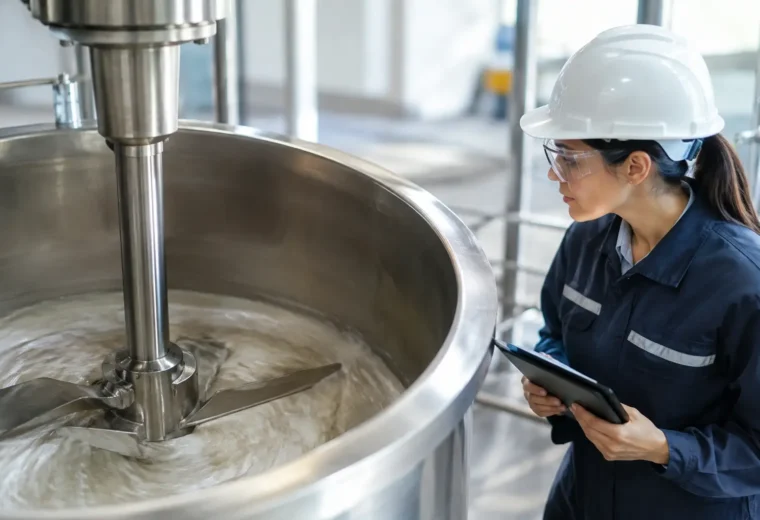
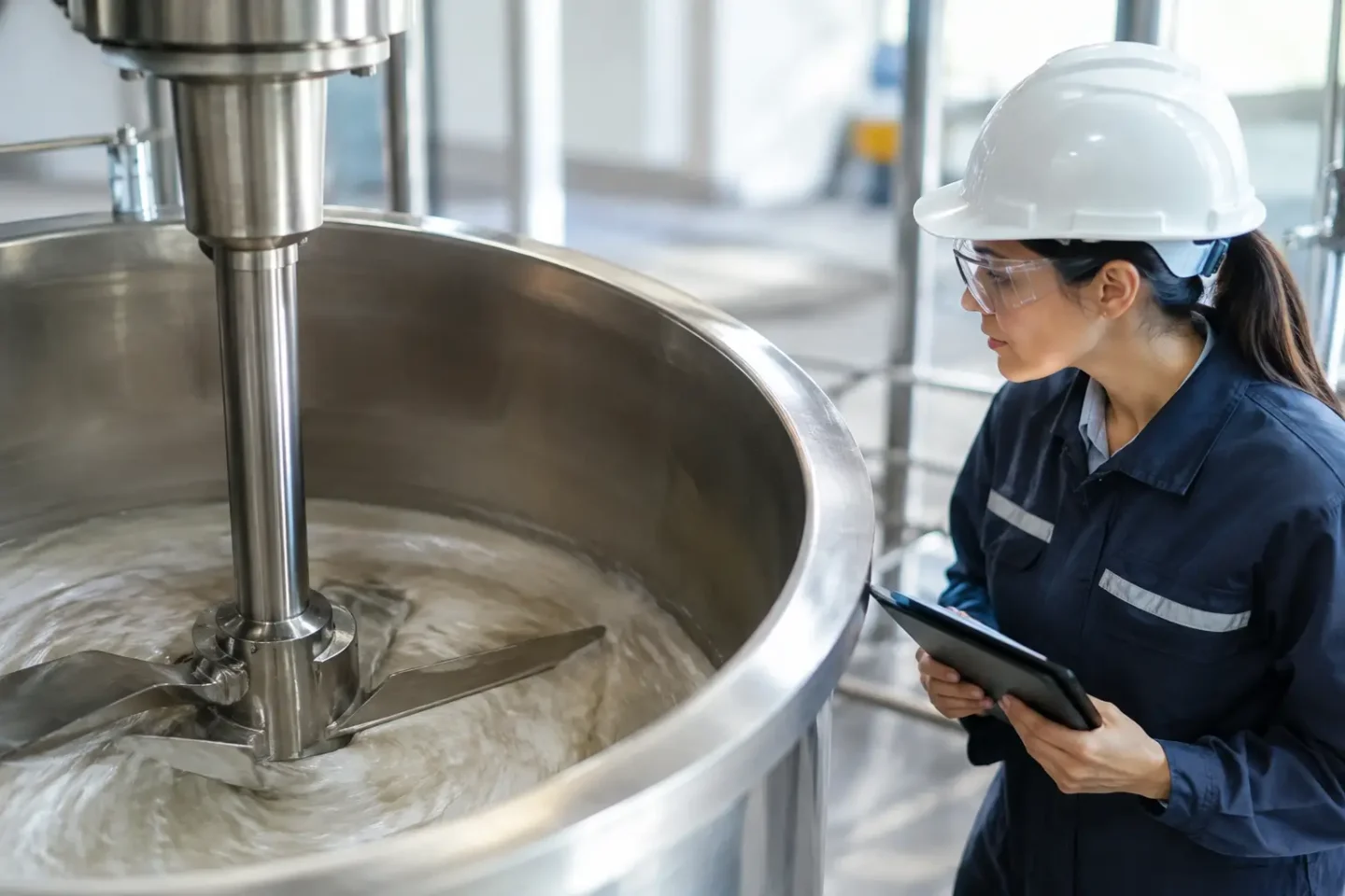
A blend can meet its target average composition and still fail in the package, at the reactor inlet, or during cleaning validation. The usual cause is not a lack of mixer horsepower. It is the presence of mixer dead zones – regions where material moves too slowly, follows a repetitive path, or remains largely isolated from the active mixing field.
For manufacturers handling powders, pastes, slurries, and high-viscosity products, these zones create more than an academic mixing concern. They can produce out-of-spec batches, ingredient carryover, excess rework, longer cycle times, and avoidable cleaning labor. Identifying them early is a process-engineering decision that protects product quality and production capacity.
What Are Mixer Dead Zones?
A dead zone is a localized area within a mixer where bulk material has insufficient circulation, shear, turnover, or exchange with the rest of the batch. The term can be misleading because material in the zone may not be completely stationary. It may move, but only as a compact mass or in a limited loop that does not provide meaningful distributive mixing.
Dead zones often occur near vessel walls, corners, shaft seals, agitator hubs, end plates, discharge ports, and the boundary between an agitator’s swept volume and the rest of the vessel. In powder mixers, they may appear as stagnant pockets beneath a shaft or along the lower shell. In viscous applications, the entire outer wall region can become poorly renewed if the agitator does not provide adequate wall wiping or close-clearance action.
The process consequence depends on the formulation. A small unmixed pocket may have little effect in a forgiving commodity blend. In a nutraceutical premix, battery slurry, catalyst formulation, adhesive, specialty chemical, or pharmaceutical product, the same pocket can create a major quality, safety, or compliance issue.
Why Mixer Dead Zones Develop
Dead zones result from the interaction of equipment geometry, material behavior, and operating conditions. A mixer design that produces excellent movement with free-flowing granules may perform poorly with cohesive powder, wet agglomerates, or a product whose viscosity rises during the batch.
Geometry Does Not Match the Mixing Duty
Every agitator generates a distinct flow pattern. Ribbon mixers move material in opposing axial directions while promoting radial circulation. Paddle and plough mixers create more energetic mechanical fluidization for many powders and wet mixtures. Planetary, sigma, and multi-shaft mixers are designed to sweep and work high-viscosity materials that do not flow readily on their own.
Problems arise when the agitator’s working envelope does not reach the regions where material accumulates. Excessive clearance between the mixing element and vessel wall, an ineffective end-wall design, poorly located baffles, or an oversized vessel can leave low-energy regions in the batch. A mixer should not be selected only by total volume, motor size, or nominal mixing time. Its flow pattern must suit the actual material and fill level.
Material Properties Change the Flow Field
Powder flowability, particle size distribution, bulk density, moisture content, electrostatic behavior, and cohesiveness all affect circulation. Fine cohesive powders can bridge, cling to surfaces, and resist migration into low-energy areas. Large density differences can cause segregation after an apparently successful mixing cycle. Liquid additions can create localized wet lumps that remain intact because the bulk bed does not repeatedly expose them to the mixing elements.
For liquid, paste, and slurry applications, viscosity is often the controlling variable. Newtonian fluids may circulate effectively with a conventional impeller arrangement, while shear-thinning, yield-stress, or thixotropic products can leave stationary material near walls and vessel bottoms. As viscosity changes with temperature, reaction progress, evaporation, or solids loading, a previously acceptable mixer can develop dead zones during the same batch.
The Mixer Is Operated Outside Its Effective Range
Even correctly specified equipment has an operating window. Underfilling a horizontal mixer can prevent the product from engaging fully with the agitator. Overfilling can restrict the free volume required for turnover and folding. Running too slowly may not generate sufficient material movement, while excessive speed can create air entrainment, particle attrition, heat buildup, or centrifugal slip where material rides the wall rather than circulating.
Ingredient addition also matters. Introducing a minor ingredient, pigment, binder, or liquid directly into a low-movement region makes uniformity harder to achieve. Addition location, feed rate, spray pattern, and the point in the cycle when an ingredient is added should be treated as part of the mixing process, not as secondary details.
The Operational Cost of Mixer Dead Zones
The visible symptom is often blend variation, but the financial impact extends across the production line. When operators compensate for inconsistent samples by extending the mixing cycle, throughput declines. When batches require reblending, screening, or disposal, labor and material costs rise. When material remains in corners or around discharge components, product recovery falls and cleaning time increases.
Dead zones also complicate quality investigations. A top sample may pass while a sample collected near the discharge or late in the batch fails. This creates uncertainty about whether the issue is raw material variation, sampling error, segregation, or mixing performance. Without understanding the material flow pattern, facilities can spend significant time changing recipes or specifications when the underlying issue is mechanical.
Cleaning is another critical exposure. Product retained in poorly swept regions can become a cross-contamination risk, particularly for allergen-sensitive food products, active ingredients, pigments, and high-value specialty formulations. A design that is difficult to clean may still be acceptable for a dedicated line. It is less suitable for frequent product changeovers or validated multiproduct service.
How to Identify Mixer Dead Zones
A reliable assessment combines process observation, test data, and engineering analysis. Relying on a single sample after a standard mix time is rarely enough. The objective is to understand whether all material zones participate in the process and whether the blend remains uniform through discharge.
A practical investigation should include representative materials and realistic operating conditions. Test at the intended batch size, mixing speed, ingredient order, and liquid-addition rate. If the process experiences seasonal humidity changes or a wide raw-material specification range, test those conditions as well.
Useful methods include:
- Multi-location sampling from top, center, ends, near the discharge, and across the discharge stream to identify spatial variation.
- Tracer studies using a detectable ingredient, colorant, salt, or other approved marker to measure distribution and turnover.
- Residence-time assessment to determine whether material near the discharge exits too early or stagnant material remains too long.
- Visual inspection and cleanout review to locate retained material after discharge and after cleaning.
- Process modeling or trials to evaluate agitator geometry, clearances, baffles, and speed before committing to a full-scale design.
No test method is universal. Color tracers can be useful for coarse powder evaluations but may not reveal a low-dose potency issue. Conductivity testing can be effective in liquid systems but may not represent the dispersion of insoluble solids. The test must reflect the quality attribute that actually matters to the product.
Engineering Solutions for Mixer Dead Zones
Correcting a dead zone starts with the severity of the problem. Small retained areas may be addressed through operating changes, while persistent nonuniformity may require a different mixer configuration or a broader process redesign.
For an existing mixer, evaluate batch fill level, agitator speed, mixing sequence, and ingredient addition points before modifying hardware. A revised liquid injection location or a controlled spray system can eliminate wet pockets that additional mixing time never resolves. Adjusting the discharge procedure can also reduce hold-up and prevent segregated material from entering downstream equipment.
When geometry is the root cause, hardware changes may include close-clearance agitators, wall scrapers, revised paddles or ploughs, improved end-wall coverage, choppers for agglomerate breakdown, or a discharge valve designed to minimize retained material. These changes must be evaluated as a system. Increasing shear may improve dispersion but can damage fragile particles, raise product temperature, or alter particle size distribution.
In demanding applications, the best answer may be a different mixing technology. A plough mixer may provide the mechanical fluidization needed for cohesive powders. A double planetary or multi-shaft mixer may be better suited to a high-viscosity paste that requires full vessel coverage. Vacuum capability may be necessary where air removal affects density, wetting, or final product performance. The correct choice depends on the material rheology, required uniformity, cleaning standard, batch range, and downstream process.
PerMix approaches this decision from the process outward: characterize the material, define the performance target, then engineer the mixing system around the real manufacturing duty. That approach avoids treating a dead zone as a simple speed or horsepower problem when the underlying issue is flow behavior.
Design for Verification, Not Assumption
A mixer should be validated at conditions that represent routine production, not only at a favorable trial point. Establish acceptance criteria for blend uniformity, mixing time, temperature rise, particle integrity, discharge recovery, and cleaning performance. Then confirm repeatability across multiple batches and expected material variation.
For new projects, pilot testing is often the most economical way to reduce risk. It can expose dead-zone behavior before a production vessel is fabricated, while there is still flexibility to change agitator design, vessel geometry, or the overall process sequence. For installed systems, a structured diagnostic study can distinguish a true mixer limitation from problems caused by feeding, upstream agglomeration, or downstream segregation.
The most productive next step is to map where material moves, where it remains, and what that behavior costs the operation. Once those answers are measured, the path to better uniformity, faster cycles, and more reliable cleaning becomes an engineering decision rather than a trial-and-error exercise.